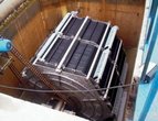
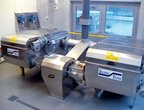
AS-VARIOcomp D (400 – 5,000 PE)
AS-VARIOcomp D (400 – 5,000 PE)

The wastewater treatment plant designated as the AS–VARIOcomp D is designed for towns and villages with 400 to 5,000 population equivalents (PE). In the design we applied our experience with previously supplied custom-made treatment plants and we put the priority on the stability of the treatment process, supported by low-load activation; high treatment efficiency, based on an innovative arrangement of the technology in the secondary settlement tank; and the minimization of operating costs that are mostly related to the final sludge stage.
Advantages of the AS-VARIOcomp D
- High stability and efficiency of the treatment process
- Possibility of a modular extension of the technology
- Minimal operating costs
- Minimal requirements for the built-up area
- Low noise
- Automated operation with low operating requirements
- Reduced investment costs
Photo Gallery


General description, inlet and outlet parameters
The designed technology combines mechanical and biological processes of wastewater treatment, to optimize overall wastewater treatment efficiency in relation to energy demands. The common elements of the AS-VARIOcomp D line are the following technological units:
- Inlet pumping station
- Mechanical pre-treatment
- Low-load activation, designed with a front-end de-nitrification zone
- Square secondary settlement tank with vertical flow
- Device for the dehydration of excess sludge - “spiral dehydrator”
- Outlet flow meter
The sizing and calculation of the line are based on the specific production of wastewater, polluting substances, and load values, in accordance with the latest legislative requirements. The AS–VARIOcomp D WWTPs are designed for 1,000, 2,000, 3,000, 4,000 and 5,000 PE in the standard versions (400–800 PE are already normally supplied); however, any size between the standard types, or a larger WWTP, can be produced without any difficulty. The guaranteed quality parameters of the treatment plant outlet comply with the parameters required by Government Regulations No. 61/2003 Coll. and 229/2007 Coll., not only for pollution source sizes up to 2,000 PE, but also for categories exceeding 2,000 PE.
Design parameters
|
Specific pollution production at the inlet |
|||||
|
Parameter |
BOD5 |
COD |
Solids |
Solidstotal |
Ptotal |
|
Unit |
g / EO • day |
||||
|
Value |
60 |
120 |
55 |
11 |
2,5 |
|
Loading parameters of standard WWTP types |
||||||
|
PE number |
PE |
1000 |
2000 |
3000 |
4000 |
5000 |
|
Q24 |
m3/d |
165 |
330 |
495 |
600 |
825 |
|
Qh |
m3/h |
19,9 |
38,0 |
57,0 |
76,0 |
87,5 |
|
BOD5 |
kg/d |
60 |
120 |
180 |
240 |
300 |
|
COD |
120 |
240 |
360 |
480 |
600 |
|
|
Solids |
55 |
110 |
165 |
220 |
275 |
|
|
Solidstotal |
11 |
22 |
33 |
44 |
55 |
|
|
Ptotal |
2,5 |
5 |
7,5 |
10 |
12,5 |
|
|
Emission standards of wastewater pollution, in accordance with Govt. Reg. 61/2003 Coll. and 229/2007 Coll. |
||||||||||
|
WWTP Category |
COD |
BOD5 |
Solids |
N-NH4+ |
Ptotal |
|||||
|
p |
m |
p |
m |
p |
m |
Average |
m |
Average |
m |
|
|
Up to 2,000 PE |
125 |
180 |
30 |
60 |
40 |
70 |
20 |
40 |
- |
- |
|
2,001 and greater PE |
120 |
170 |
25 |
50 |
30 |
60 |
15 |
30 |
3 |
8 |
– Where the p values for the COD, BOD5, and Solids parameters refer to acceptable concentrations
– Where the m values must not be exceeded
|
Emission standards of wastewater pollution, in accordance with Gov’t. Reg. 61/2003 Coll. and 229/2007 Coll. |
||||||||||||||
|
WWTP Category |
COD |
BOD5 |
Solids |
N-NH4+ |
N-NO3- |
Solidstotal |
Ptotal |
|||||||
|
p |
m |
p |
m |
p |
m |
Average |
m |
Average |
m |
Average |
m |
Average |
m |
|
|
1000 PE |
80 |
120 |
15 |
25 |
20 |
35 |
5 |
12 |
25 |
35 |
35 |
45 |
2 |
6 |
|
2000 PE |
70 |
110 |
10 |
20 |
20 |
35 |
5 |
12 |
25 |
35 |
35 |
45 |
2 |
6 |
|
3000 PE |
70 |
100 |
10 |
20 |
15 |
30 |
4 |
10 |
20 |
30 |
30 |
40 |
2 |
6 |
|
4000 PE |
60 |
90 |
10 |
20 |
15 |
30 |
4 |
10 |
20 |
30 |
30 |
40 |
2 |
6 |
|
5000 PE |
60 |
90 |
10 |
20 |
15 |
30 |
4 |
10 |
20 |
30 |
30 |
40 |
2 |
6 |
In the case of extremely high requirements for outflow parameters, a design for the insertion of a membrane technology (MBR) can be prepared and submitted.
|
Usually achieved parameters after precipitation and MBR |
||||||||||||||
|
WWTP Category |
COD |
BOD5 |
Solids |
N-NH4+ |
N-NO3- |
Solidstotal |
Ptotal |
|||||||
|
p |
m |
p |
m |
p |
m |
Average |
m |
Average |
m |
Average |
m |
Average |
m |
|
|
1000 –5000 |
20 |
40 |
5 |
10 |
1 |
5 |
5 |
10 |
15 |
25 |
20 |
35 |
1,5 |
3 |
– MBR can be used as an optional modular extension of the AS–VARIOcomp D.
Description of the technology of the AS–VARIOcomp D
The first part of the machine’s technological unit is a circular pumping station. The station is produced in two types of different sizes, having a boundary at 2,500 PE. The pumping stations are equipped with a rough rack basket and a lifting device. For the pumping of wastewater for up to 1,400 PE, two pumps with alternating operation are used, while for over 1,400 PE there are three pumps with cyclic operation.
Mechanical pre-treatment is done with self-cleaning screw racks with machine scraping. Separated screenings are collected in a screening container. The manually scraped racks in the bypass represent a backup. Mechanically pre-treated water flows by virtue of gravity to the dividing structure before the biological part of the WWTP. In treatment plants where the reduction of the phosphorus content in drained wastewater is required, the precipitation of phosphorus by the dosing of precipitant in the stream of inflowing water, before the dividing structure, is proposed.
The activation part consists of nitrification and front-end de-nitrification. Internal recirculation is introduced between the tanks, which ensures the reduction of the outlet concentration of nitrate nitrogen. For treatment plants for under 2,000 PE, the internal recirculation is ensured by means of mammoth pumps; in larger plants internal recirculation pumps are employed. The de-nitrification tanks are fitted with low-speed submersible propeller mixers on the activation device. The tanks are also equipped with fine bubble aeration elements, to enable the aeration of the tank in the period when the temperature of wastewater is lower. The aeration elements are installed on supporting pipes in each tank. In the nitrification tank, fine bubble aeration elements are installed to ensure the supply of oxygen. Single-speed blowers act as the source of oxygen for the nitrification, and in the winter period also for the de-nitrification tanks.
The secondary settlement tanks are designed as two square tanks with a vertical flow. Water flows into the secondary settlement tank via a degasification zone and stilling cylinder. Return sludge is exhausted by means of a mammoth pump, and by standard pumps in larger WWTPs. An innovation is the extraction of treated water by means of a system of submerged collectors, combined with the automatic skimming of floating sludge and the possibility of simple adjustment of the level height. The above-stated combination ensures the minimization of leaks of un-dissolved substances, thus contributing to higher efficiency.
The sludge management is designed so as to minimize operating costs. Excess activated sludge is pumped via the AS-PROchem D flocculation station directly to a spiral dehydrator that is able to condense sludge to 18 - 20% of dry matter, with minimal energy requirements. An advantage of this equipment is that it can work in a fully automatic operation. For illustration, we are "only" quoting the reaction of the investor to the first pilot unit put into actual operation more than a year ago:
We have been using the dehydrating equipment supplied by you - spiral dehydrator - for more than approx. 12 months. During this time period, the WWTP operation (2,500 PE) has yielded considerable savings amounting to about CZK 30,000 per month. The savings result from a reduction of the quantity of sludge transported from the WWTP.
During the installation and operation of the equipment, we were provided with 100% expert support by the supplier. During the period of use there has not been any defect or failure of the dehydration equipment working in the fully automatic mode. The operation of the dehydration equipment is simple and easy. The WWTP operators are very satisfied with it.
Ing. Jan Helikar – Mayor
Operation automation The control system of the treatment plants of the AS-VARIOcomp D line is fully automatic, incl. inflow pumping, the pumping of return and excess sludge, sludge extraction ,and synchronization with the operation of the final sludge stage (spiral dehydrator).
Automatic control of the entire system is ensured through:
- Timing for plants for under 2,000 PE
- Oxygen sensors for plants for over 2,000 PE
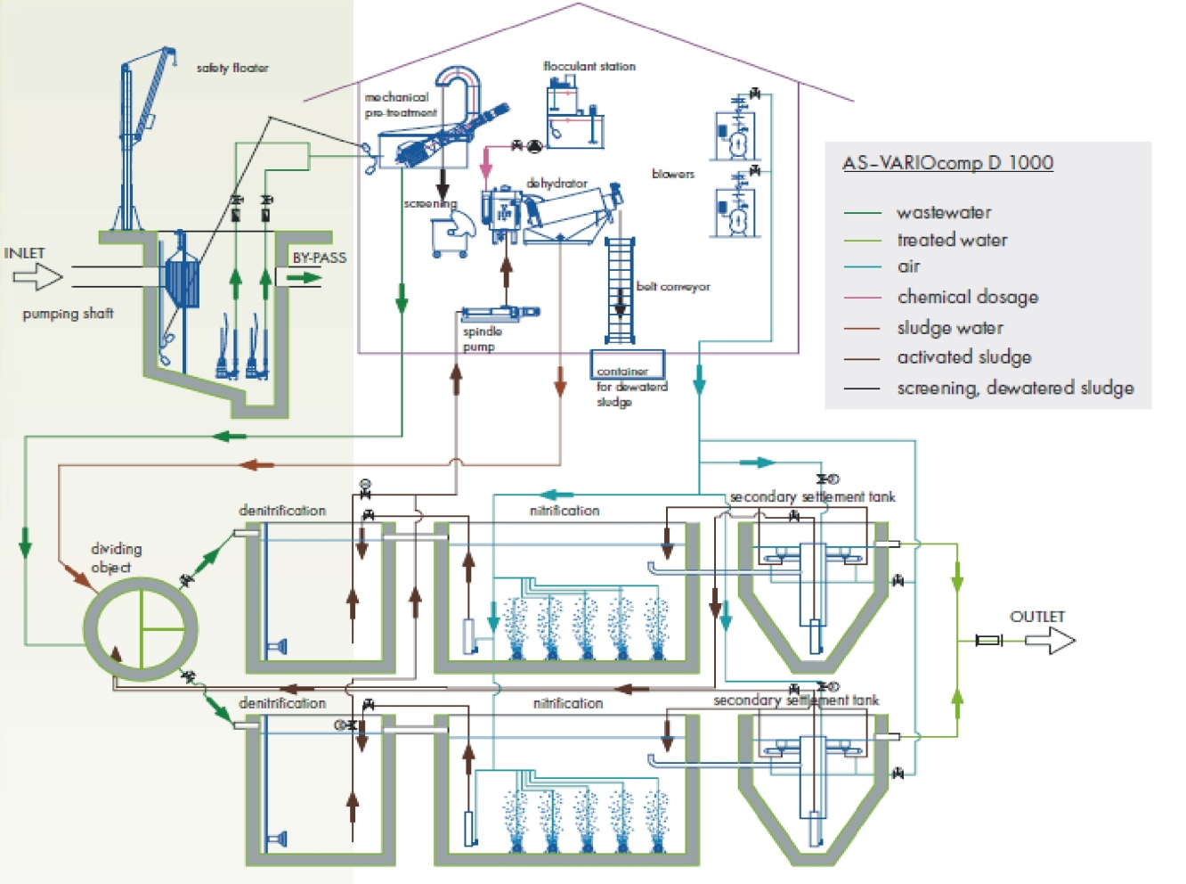
Technological diagram of a 1,000 PE WWTP - AS-VARIOcomp 1000 D

Optional modular technology extension
Besides the chemical precipitation of phosphorus and the membrane technology, the system may be extended with a rainwater holding tank, a cesspit, or by modifying the technological design to a system with regeneration, in the case of operational stability requirements or other structures.
Device for the chemical precipitation of phosphorus If the Ptotal limit needs to be met in a WWTP for under 2,000 PE, we are able to achieve these limits in all WWTPs by means of a device for the chemical precipitation of phosphorus.
Membrane technologies In the case of high outlet parameter requirements, a design with wastewater treatment by means of the membrane technology may be prepared and submitted. Mechanically pre-treated wastewater is biologically treated and then un-dissolved substances are removed from it by means of membranes. The size of the pores in the membranes is in the order of microns. Bacteria and most viruses will not penetrate into the filtrate (permeate). An advantage of water treated in this manner is that the drained water is hygienically treated and can be recycled or infiltrated.
What we have verified in practice is that microbiological indicators for a WWTP with membrane filtration achieve a quality enabling reuse, e.g., as service water (see the table below).
|
Bacteriological analysis of water drained from MBR |
|||
|
Unit |
Analysis 1 |
Analysis 2 |
|
|
Escherichia coli |
CFU in 100 ml |
0 |
0 |
|
Coliform bacteria |
CFU in 1 ml |
0 |
5 |
|
Intestinal enterococci |
CFU in 1ml |
0 |
0 |
|
Determination of clostridia |
CFU in 50 ml |
0 |
0 |
|
Cultivable bacteria at 22° C |
CFU in 1 ml |
530 |
|
